
Draw beautiful digital electronics timing diagrams in LaTeX
Today, for one of my engineering courses, I had to create some timing diagrams to show certain parts of the PCI standard. If you’ve never had to draw your own timing diagrams before, then you probably haven’t realized that there is no obvious to quickly, easily draw waveforms for a bunch of signals.
The solution I found is tikz-timing. An alternative is timing.sty, which is simple and pretty enough in a pinch.
I find the more advanced features of tikz-timing invaluable for versatility, though—there’s nothing like needing to talk about a signal transition in some text, and, oh yeah, just drawing the signal in the text.
The only problem with tikz-timing is a shortage of examples. The package documentation has but a handful, and they don’t look much like real-world timing diagrams. The texample.net timing diagrams are just copied directly from that manual, which isn’t useful. So I figure I’ll post some realistic use cases.
To get started, I included the package like this:
\usepackage{tikz-timing}[2014/10/29]
\usetikztiminglibrary[rising arrows]{clockarrows}
Then I defined a command so I could reference a bus:1
\usepackage{xparse} % NewDocumentCommand, IfValueTF, IFBooleanTF

% Reference a bus.
%
% Usage:
%
%     \busref[3::0]{C/BE}    ->   C/BE[3::0]
%     \busref*{AD}           ->   AD#
%     \busref*[3::0]{C/BE}   ->   C/BE[3::0]#
%
\NewDocumentCommand{\busref}{som}{\texttt{%
#3%
\IfValueTF{#2}{[#2]}{}%
\IfBooleanTF{#1}{\#}{}%
}}
The PCI timing diagrams are drawn with reference to version 2.2 of the PCI specification.
I added the DEVSEL# signal myself,2 and I’ve taken some slight liberties with the start and stop times of the signals (though they should still be accurate).
One notable feature lacking in my diagrams is the delay cycles—most books you’ll read on PCI, in addition to the spec itself will include those directly on the diagram. I haven’t figured out how to do that kind of thing yet.
PCI Read
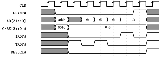
\begin{tikztimingtable}[%
    timing/dslope=0.1,
    timing/.style={x=5ex,y=2ex},
    x=5ex,
    timing/rowdist=3ex,
    timing/name/.style={font=\sffamily\scriptsize}
]
\busref{CLK}         & 18{c} \\
\busref*{FRAME}      & 2u 6L H U \\
\busref[31::0]{AD}   & 2u 1D{addr} 1U{} 1D{$d_1$} D{$d_1 '$} D{$d_2$} 2D{$d_3$} U \\
\busref*[3::0]{C/BE} & 2u 1D{0010} 6D{BE\#} U  \\
\busref*{IRDY}       & UU 4L HLH \\
\busref*{TRDY}       & UU HLH 3L H \\
\busref*{DEVSEL}     & 2U 6L H\\
\extracode
\begin{pgfonlayer}{background}
\begin{scope}[semitransparent ,semithick]
\vertlines[darkgray,dotted]{0.5,1.5 ,...,8.0}
\end{scope}
\end{pgfonlayer}
\end{tikztimingtable}
You can think of the tikztimingtable environment as two-column tables with some special syntax for the righthand column. The gist of it is this: there are signal variants, and you create them by writing a letter that serves as a key. Each key has two variants: a half-duration lowercase one and a full-duration uppercase one.
So to make the clock signal in the PCI read diagram, it’s 18 half-duration clock cycles, and we write that 18{c}. The brackets there aren’t strictly necessary, but you can write them for clarity.
Signal changes are separated by spaces if there’s any ambiguity about what argument goes with what transition.
In the above example, I used these letters to make the signals:
C/c: clockU/u: unknownD/d: multiple valuesH/h: hiL/l: lo
The other interesting option is including letters in the D timings.
The way you do that is you add an argument in brackets following a D block, like D{0000} to draw a multi-signal timing with value 0000.
For invalid states I used X in the below example:
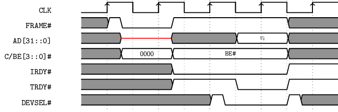
PCI Interrupt Acknowledge
When a PCI interrupt acknowledge starts, you have invalid values in the address/data line.
They’re knowable, but it’s against the protocol to use them for anything.
To show that I used an X, which draws a red line for an undefined don’t care. Or at least that’s how I interpreted it.
Some people will just use shaded blocks for everything, and make no distinction between the two.
\begin{tikztimingtable}[%
timing/dslope=0.1,
timing/.style={x=5ex,y=2ex},
x=5ex,
timing/rowdist=3ex,
timing/name/.style={font=\sffamily\scriptsize}
]
\busref{CLK} & 10{C} \\
\busref*{FRAME} & U h l L l h 4H 2U \\
\busref[31::0]{AD} & U u 2X 2.5U 2D{$v_i$} 2U \\
\busref*[3::0]{C/BE} & U u 2D{0000} 4.5D{\busref*{BE}} 2U \\
\busref*{IRDY} & 3.5U 4.5L 2H \\
\busref*{TRDY} & 3.5U 2.5H 2L 2H \\
\busref*{DEVSEL} & 5U hl 2L h 1.5U \\
\extracode
\begin{pgfonlayer}{background}
\begin{scope}[semitransparent ,semithick]
\vertlines[darkgray,dotted]{1.0,3.0,...,9.0}
\vertlines[gray,dotted]{2.0,4.0,...,8.0}
\end{scope}
\end{pgfonlayer}
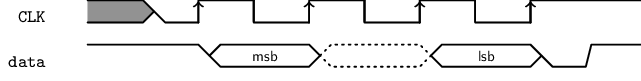
\end{tikztimingtable}Synchronous Serial Interface
Synchronous Serial Interface (SSI) is another protocol I studied. I drew a genuinely oversimplified diagram of it, just for fun.
\begin{tikztimingtable}[%
    timing/dslope=0.4,
    timing/.style={x=5ex,y=2ex},
    x=3ex,
    timing/rowdist=4ex,
    timing/c/rising arrows,
    timing/name/.style={font=\sffamily\scriptsize},
]
\busref{CLK}  &  U8{C}H\\
\busref{data} & Hhh2D{msb};[dotted] 2D{};  2D{lsb}LH\\
\end{tikztimingtable}
The images you saw on this page were compiled with pdfTeX version 3.14159265-2.6-1.40.15 (TeX Live 2014/Arch Linux) and converted from PDF to PNG with ImageMagick convert.
Defining commands for patterns of input is one of those tricks you pick up once you’ve used LaTeX for more than a handful of documents. The advantage of doing it this way is that if I want to change the convention used to represent the logic level of my signals, I can just change it in one place and it gets updated in the rest of the document.↩︎
So it might be wrong—go read the spec if you really care.↩︎
